
| Installing a Little Tarheel HF antenna on an 80 series Land Cruiser
|
||
I initially installed a Yaesu FT1802 2m only rig in our 80. It was cheap and easy to install and got us on the air. The 80 became the 'base' while on camping trips and we used 2m HT's to communicate back to the base when on hikes.
Then came the urge to install a more flexible rig and I found myself drawn to the Yaesu FT857D - lots of radio for the buck. An all in one VHF/UHF/6m/HF all mode radio that was compact and reasonably priced. Lots of good reviews on the net and it seemed like the way to go. I kept my eye out until I found it on sale and also discounted. Ordered it along with the full function microphone. The rig came with the separation kit bundled in so I had everything necessary for the install (except the HF antenna). Since I already had installed the 2m rig before I had an VHF/UHF antenna already in place and ready to go. All that was necessary was to select a HF antenna and install it.
More searching on the web brought the Little Tarheel to my attention. Again excellent reviews for the size of antenna versus performance and durability. So a quick phone call to the folk at Tarheel and the antenna was on its way to me. The Little Tarheel is a "screwdriver" antenna - a style of antenna that uses a base loading coil that can be adjusted via an internal motor. A simple up/down switch allows the antenna to be raised/lowered as necessary from a remote location. There are fancy automatic tuner controllers that can be interfaced to the rig and the antenna to allow it to be automatically tuned. I have found that it can also be easily tuned by 'ear', see later.
|
||
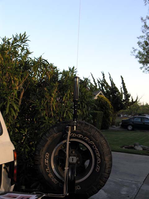 |
After welding up a bracket to install in the Kaymar light post the Tarheel was mounted using an off the shelf 3/8" insulated stud mount with coax cable. The height of the bracket was set to clear the tyre and to allow the top of the screwdriver antenna to just clear the top of the roof line. That allows the whip to be removed and the antenna is then level with the roofline and thus protected. The whip is easy to install or remove from the antenna housing. With the screwdriver nearly fully retracted the antenna is resonant in the 6m band. Extending the antenna tunes the antenna to the lower bands. Of course the question is how to tune/adjust the antenna for the band you are interested in working? See below (end of this webpage). |
|
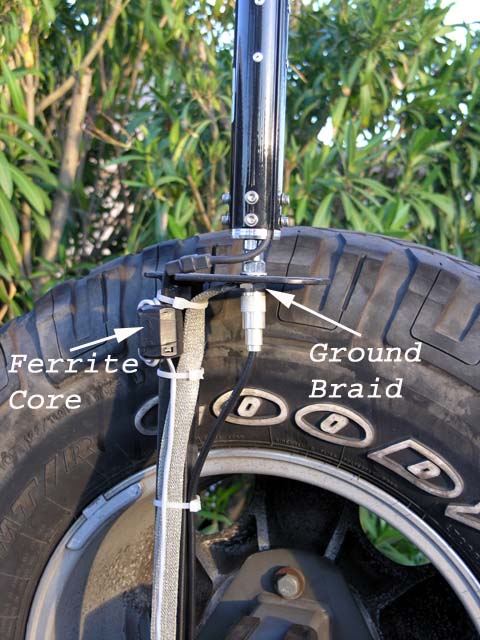 |
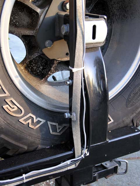
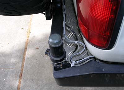
A close up picture showing the custom bracket, the coax connection, the base of the Tarheel and the braided ground strapping and finally the control cable for the motor in the screwdriver. The ferrite core is provided by Tarheel and they recommend installing it as close as possible to the connector to prevent RF from getting into the control cable during transmit. The braid provides a direct ground connection between the base of the antenna system and the chassis and body of the vehicle. While a ground is not not 'that' important with a VHF or UHF system, it is of extreme importance in a HF system. Providing a good RF ground requires careful attention to cleaning metal screw down points of paint to ensure an excellent conducting connection. I soldered ring connectors at each point where the braid would be bolted to the vehicle body and chassis. The braid terminates at the base of the antenna via a large ring tab. |
 |
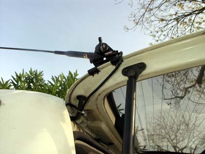
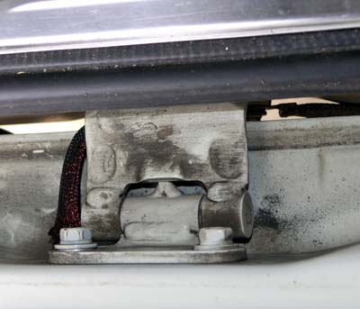
The picture to the left shows more detail of the grounding of the braid. This bolt ties the braid to the swing arm and provides a good RF ground connection to the braid and antenna system. The braid is folded over to make the 90 degree bend and the bend is soldered to keep is flat. The control cable and coax are secured with tiewraps and tiewrap blocks to provide a neat and tidy install. |
|
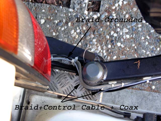 |
Picture showing the pivot for the swing arm. The braid is grounded through a tapped hole in the bumper that is bolted to the chassis. This ties the antenna to the chassis and via the braid also provides the RF ground between the chassis and the swing arm. You can see the braid, control cable and coax following together around the pivot. This is as tight as the cables get, with the swing arm fully open. When the arm is closed there is some slack in the cables, but since they are tiewrapped to the arm and bumper the slack stays neatly in control. The braid goes under the vehicle and connects to the body via a body side hinge bolt. This ensures the body and chassis a tied together right at the rear of the vehicle. |
|
 |
Further grounding of the lower and upper tail gates with more braid, otherwise they were only grounded via their respective hinge pins. Upper tailgate grounded via a bolt on tailgate side of the hinge to a lift strut bolt on the body. All paint was ground away from the contact points on the bolt and body using a dremel and sandpaper pad. Spring washers were added where appropriate to 'bite' into the contact surfaces. |
|
 |
Lower tailgate hinge. Another section of copper braid bolted from the tailgate side to the body side via the hinge bolts. On the top right of the picture you can just see a section of braid terminating at the lower hinge bolt. The section heading off to the right is the body end of the braid that runs all the way up to the HF antenna base. |
|
 |
The braid, control cable and coax with the tyre swing arm in the closed position. The cables sit nicely in their 'slack' position. |
|
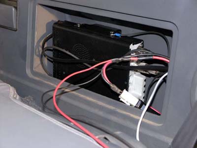 |
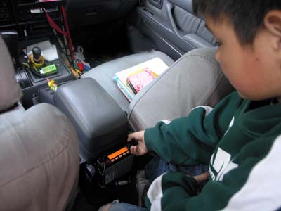
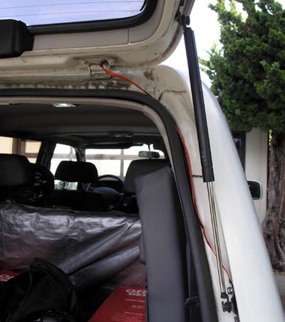
The FT857D installed in the rear cubby of the 80. You can just see (blue ring terminal and black wire) an additional ground connection from the rig that goes to the body of the vehicle. The cubby is insulated from the rear cavity and so I drilled some access holes with grommets to run the power, coax, control cable, separation kit cables etc into the cavity. This keeps the rig in a relatively dust free and water proof area of the vehicle. |
|
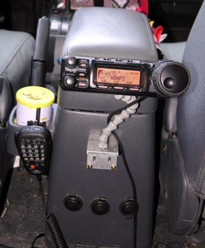 |
The rig's head installed on some locline. The locline allows the head to be adjusted/rotated as needed for easy viewing. The mike is mounted on the provided bracket to the rear 'cup holder'. You can also see the additional three 12V outlets in the lower portion of the console. The outlets are always powered from the auxiliary battery and are individually fused in the engine bay. Since my kids are also licensed, it is handy to have the rig and mike easily accessible from their seats since they are often using the rig when we are driving. |
|
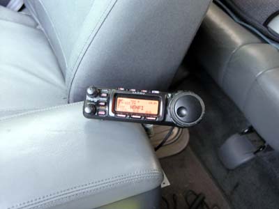 |
The head rotated to be visible and accessible from the driver's seat. This would be my view when sitting in the driver's seat. The nice thing of having the head behind the console is that it is out of the way and most time folk don't even notice it is in the vehicle. |
|
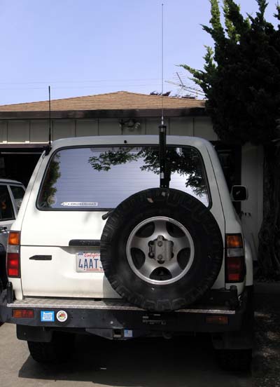 |
The view of the installed Little Tarheel antenna on the right and the VHF/UHF antenna on the top left of the tailgate. Ok, now on to how to tune the antenna. I have found that it is pretty easy to tune by ear. With the HF tuned to the band of interest and the rig set to AM you can just listen to the background noise as you adjust the antenna and you set it for maximum background noise. The antenna is then resonant. Make sure you have the FT857D set to display SWR on its meter. You can also plug a small ammeter (1mA movement) into the jack on the head. It will display the same information as the digital display on the head. Then you can just set the output to say 10W and key the transmitter (still on AM) and adjust the antenna for minimum SWR. You'll find the SWR is already pretty close to minimum based on the previous tuning via maximum background audio volume. If I get bored or tired of the manual tuning I'll see about making an autotuner. I have a few ideas how to implement my own. |